How to Reduce a Complex Control Block Diagram
TL;DR
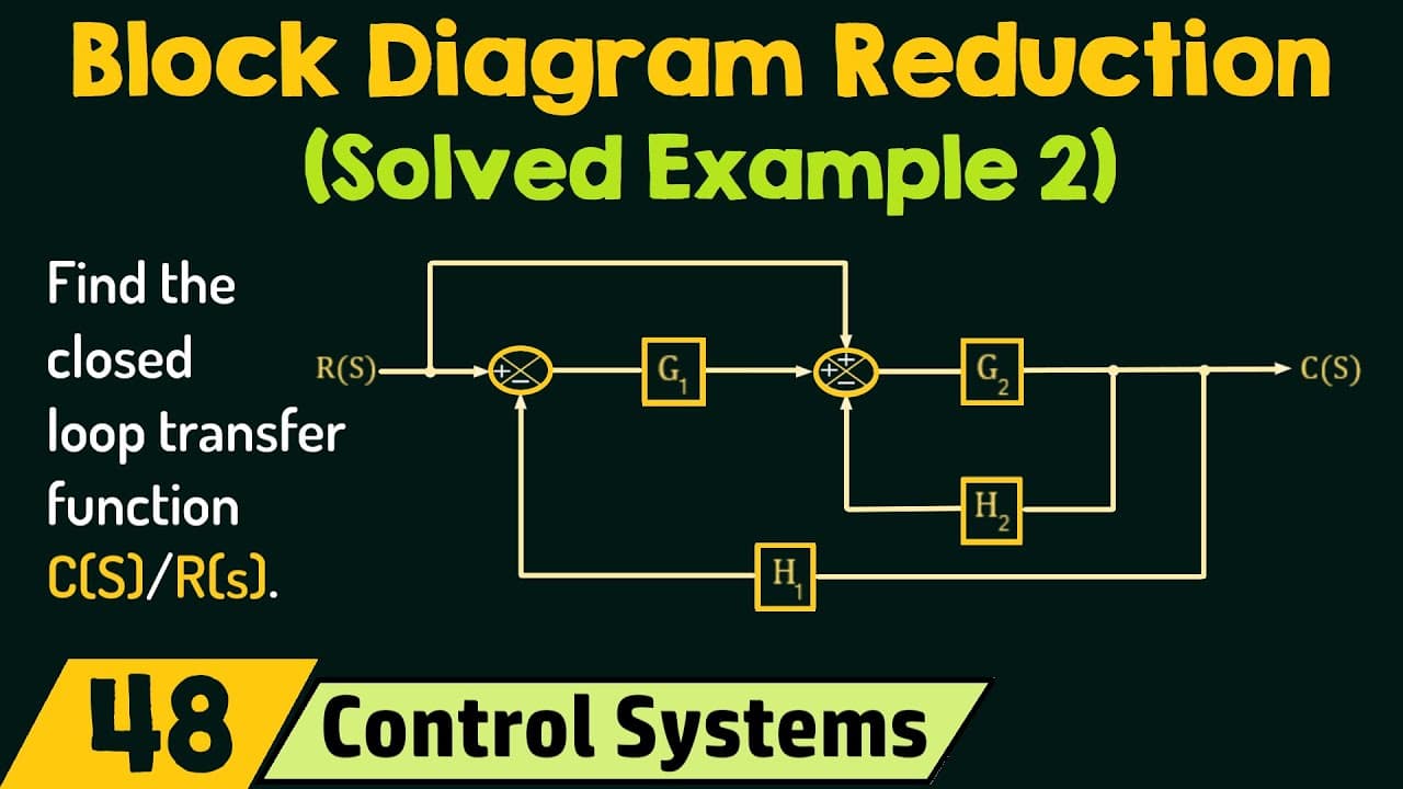
Split the three-input summing point into two two-input summing points before reducing the negative feedback loops. After shifting and rearranging adders, combining series and parallel blocks, and simplifying both feedback loops, the closed-loop transfer function is C(s)/R(s) = (1 + G1(s))G2(s) / (1 + G2(s)H2(s) + G1(s)G2(s)H1(s)).
Transcript
in the previous lecture we have discussed one example based on block diagram reduction now in this presentation we are going to discuss one more example based on block diagram reduction so let's get started using the block diagram reduction technique determine the closed loop transfer function cs over rs we are given a block diagram representation ... Read More
Key Insights
- A three-input summing point can be replaced by two two-input summing points because both arrangements produce the same algebraic output. For inputs R1, R2, and R3, the first adder produces R1 + R2, and the second adds R3 to produce R1 + R2 + R3.
- The original inner loop cannot be reduced directly with the standard negative-feedback formula because its summing point has an additional input from a takeoff point. Splitting that summing point isolates a conventional two-input feedback structure while preserving every original signal contribution and sign.
- The inner negative-feedback loop has forward-path gain G2 and feedback-path gain H2 after the summing point is split. Applying the negative-feedback formula replaces this loop with a single equivalent block whose transfer function is G2 divided by 1 + G2H2.
- Shifting a summing point after the G1 block requires multiplying the shifted side input by G1. This adjustment preserves the signal relationship that existed before the move and creates a configuration in which the remaining feedback structure can be identified and reduced.
- The rearranged system contains a negative-feedback loop with forward gain G2 divided by 1 + G2H2 and feedback gain G1H1. Simplifying its closed-loop expression gives G2 divided by 1 + G2H2 + G1G2H1.
- The unity branch and the G1 block form parallel paths because both connect the same takeoff point to the same summing point. Their gains therefore add, allowing the two paths to be replaced by one block with gain 1 + G1.
- The final two equivalent blocks are connected in series, so their gains multiply. Combining the parallel equivalent 1 + G1 with the reduced feedback block produces (1 + G1)G2 divided by 1 + G2H2 + G1G2H1.
- The block diagram reduction process depends on changing the diagram without changing its input-output relationship. Splitting summing points, shifting an adder with the required gain adjustment, rearranging adders, and combining feedback, parallel, and series elements progressively converts the system into one block.
Install to Summarize YouTube Videos and Get Transcripts
Explore YouTube Video Summarizer or Get YouTube Transcript Extractor
Questions & Answers
Q: How do you start reducing this control-system block diagram?
Start by examining the three-input summing point inside the portion that appears to form a negative-feedback loop. The loop cannot be reduced immediately with the standard formula because that formula is applied to a two-input summing point. Split the three-input point into two two-input summing points, preserving all signal signs and contributions, so the inner loop becomes a conventional negative-feedback structure.
Q: How can a three-input summing point be split into two adders?
Connect two of the inputs, such as R1 and R2, to the first two-input adder. Its output is R1 + R2. Feed that result into a second two-input adder and connect R3 as the other input. The final output becomes R1 + R2 + R3, which is identical to the output of the original three-input summing point.
Q: What is the equivalent transfer function of the inner feedback loop?
After splitting the three-input summing point, the inner loop is a standard negative-feedback system with G2 as its forward-path gain and H2 as its feedback-path gain. Using the stated negative-feedback formula, G divided by 1 + GH, the loop is replaced by a single block with transfer function G2 divided by 1 + G2H2.
Q: Why is the summing point shifted after the G1 block?
The summing point is shifted after G1 to expose a reducible negative-feedback loop in the remaining diagram. When a summing point moves from before a block to after it, the affected side input must be multiplied by that block's gain. Therefore, shifting this adder after G1 introduces a gain factor of G1 on the corresponding input path.
Q: How is the second negative-feedback loop simplified?
After shifting the summing point, rearranging the adjacent adders, and combining the applicable series gains, the second loop has forward gain G2 divided by 1 + G2H2 and feedback gain G1H1. Applying the negative-feedback formula and simplifying gives an equivalent transfer function of G2 divided by 1 + G2H2 + G1G2H1.
Q: Why do the unity path and G1 path combine as 1 + G1?
The unity-gain branch and the G1 block are connected between the same takeoff point and the same summing point, so they are parallel paths. Gains in this parallel arrangement are added. Since the branch gain is unity, or 1, and the other path has gain G1, their equivalent single-block gain is 1 + G1.
Q: What is the final closed-loop transfer function C(s) over R(s)?
The final closed-loop transfer function is C(s)/R(s) = (1 + G1(s))G2(s) divided by 1 + G2(s)H2(s) + G1(s)G2(s)H1(s). It results from multiplying the final series blocks: the parallel-path equivalent 1 + G1 and the reduced feedback equivalent G2 divided by 1 + G2H2 + G1G2H1.
Q: Which block diagram reduction operations are used in the example?
The reduction uses several operations in sequence: splitting a three-input summing point into two two-input summing points, reducing an inner negative-feedback loop, shifting a summing point after G1 with the necessary gain adjustment, rearranging adjacent adders, multiplying blocks in series, reducing another negative-feedback loop, and adding the gains of parallel paths before the final series multiplication.
Summary & Key Takeaways
-
The original block diagram contains forward-path blocks G1 and G2, feedback gains H1 and H2, two adders, a takeoff point, reference input R(s), and output C(s). Direct reduction is initially blocked because one feedback loop contains a three-input summing point instead of the two-input configuration used by the standard feedback formula.
-
The three-input summing point is split into two two-input summing points without changing its output. This exposes the inner negative feedback loop with forward gain G2 and feedback gain H2. Reducing that loop produces an equivalent block with gain G2 divided by 1 plus G2H2.
-
The remaining reduction shifts an adder after G1, multiplies the affected input by G1, rearranges adjacent adders, and reduces another negative feedback loop. The parallel paths with gains G1 and unity combine to 1 plus G1, producing the final transfer function after the remaining series blocks are multiplied.
Read in Other Languages (beta)
Share This Summary 📚
Summarize YouTube Videos and Get Video Transcripts with 1-Click
Try YouTube Summary with ChatGPT & Claude or YouTube Transcript Generator
Explore More Summaries from Neso Academy 📚



Summarize YouTube Videos and Get Video Transcripts with 1-Click
Try YouTube Summary with ChatGPT & Claude or YouTube Transcript Generator