Frequency response test for thermal imaging sensor

TL;DR
The content discusses the process of creating a low-cost infrared imaging system using a thermal sensor and a shutter wheel, as well as future plans involving scanning mirrors and an Altera board for the project.
Transcript
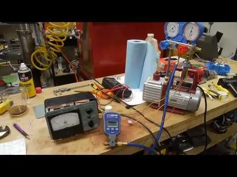
hey everyone welcome to another installment of my video series on making low-cost infrared imaging thermal imaging so today I have that sensor that I took out of the eggs Tec IR 250 and desolder the sensor from the board and mounted it inside this electrical box with a one-off amp amplifier giving us hundred hundred times gain and then I also mount... Read More
Key Insights
- 😘 Creating a low-cost infrared imaging system is possible using a thermal sensor, amplifier, and simple circuitry.
- 💆 The limitations of the thermal sensor's thermal mass become apparent when observing the signal response at different frequencies.
- 🏂 The incorporation of scanning mirrors and an Altera board offers potential for improving image quality and flexibility in adjusting scan speeds.
- 🤗 The project combines digital and analog components, providing a hands-on learning experience in various aspects of electronics.
Install to Summarize YouTube Videos and Get Transcripts
Explore YouTube Video Summarizer or Get YouTube Transcript Extractor
Questions & Answers
Q: How does the shutter wheel affect the signal response of the thermal sensor?
The shutter wheel controls the frequency at which the sensor receives thermal information. Slower speeds result in a more accurate response, while higher speeds limit the sensor's ability to reach its maximum response point.
Q: What advantages does the chopper stabilized op-amp provide in this setup?
The chopper stabilized op-amp, specifically the 80-85 35, offers low input offset voltage, ensuring accurate signal processing and reducing noise interference.
Q: What are the future plans for the project involving scanning mirrors?
Scanning mirrors will be incorporated to enable the scanning of the scene, providing the ability to adjust image clarity and contrast by changing the scan speed.
Q: How will the Altera board be utilized in the project?
The Altera board, along with a frame buffer, will be used to collect and store data from the thermal sensor. The same code will be used for both the scanning electron microscope and the thermal imaging system, and the output will be displayed on a VGA monitor.
Summary & Key Takeaways
-
The content demonstrates the setup of a low-cost infrared imaging system using a thermal sensor, amplifier, and a shutter wheel controlled by a motor.
-
The thermal sensor's response to different frequencies is observed using an oscilloscope, showing the limitations of the sensor's thermal mass.
-
Future plans involve incorporating scanning mirrors and an Altera board to improve image quality and display the output on VGA.
Read in Other Languages (beta)
Share This Summary 📚
Summarize YouTube Videos and Get Video Transcripts with 1-Click
Try YouTube Summary with ChatGPT & Claude or YouTube Transcript Generator
Explore More Summaries from Applied Science 📚


Summarize YouTube Videos and Get Video Transcripts with 1-Click
Try YouTube Summary with ChatGPT & Claude or YouTube Transcript Generator