Making my own reflow hot plate - Part 2 - Custom PCB and assembly
TL;DR
The video demonstrates assembling a PCB for a reflow plate device, improving circuitry, and testing functionality.
Transcript
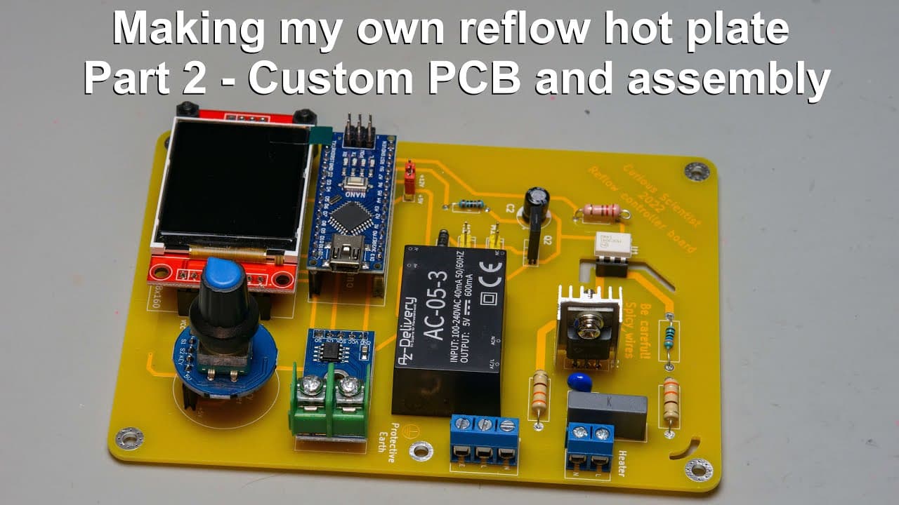
welcome everyone in this video i'm going to continue my reflow plate project so in the previous video you could see the proof of working of this device so i put together everything on a breadboard and i was able to actually solder a circuit board in fact the circuit board is right next to me so i soldered this as5600 circuit board with my freshly m... Read More
Key Insights
- ⚡ Integrating components into a single PCB design minimizes clutter and enhances the clarity of connections, especially for systems dealing with high voltage.
- 💄 The choice of vibrant-colored PCBs not only improves aesthetics but can also facilitate troubleshooting by making traces and components more distinguishable.
- 😒 Implementing standoffs for components like displays ensures better stability and reduces physical strain on solder connections during use.
- ⚡ The use of optocouplers as isolation devices ensures that the low-voltage microcontroller can safely control high-voltage operations without risking damage or creating hazards.
- 🧑🦼 Modular designs, where components like motors and sensors are easily replaceable, enhance maintainability and adaptability in future project phases.
- 👻 The trial-and-error approach during testing phases is critical, allowing the creator to refine parameters and ensure that the circuitry behaves as intended under varying conditions.
- 📽️ Tracking and documenting changes throughout the assembly process bolster project clarity, enabling easier updates and modifications later on.
Install to Summarize YouTube Videos and Get Transcripts
Explore YouTube Video Summarizer or Get YouTube Transcript Extractor
Questions & Answers
Q: What improvements were made in the PCB design for the reflow plate project?
The PCB design featured several enhancements aimed at safety and functionality. One notable improvement was the addition of physical gaps between critical traces to ensure safe separation of high and low voltage parts, especially around the optocoupler. This attention to detail reduces the risk of accidental shorts and enhances overall system reliability.
Q: Why is it important to have a neat assembly in electronic projects, especially with mains voltage devices?
Neat assembly in electronic projects, particularly those involving mains voltage, is vital for safety, functionality, and ease of troubleshooting. Proper organization minimizes the risk of shorts or interference among wires and components. A tidy assembly also aids in maintenance, reduces errors during future upgrades, and enhances the aesthetic appeal of the project.
Q: What issues did the presenter encounter during the testing phase of the circuit?
During testing, the presenter faced connectivity issues caused by faulty wiring, which led to incorrect temperature readings and erratic behavior of the thermometer. The wires were twisted improperly, which caused intermittent connections. After addressing these faults and improving the wiring, the system demonstrated successful operation and accurate temperature readings.
Q: How did the creator ensure safety when working with high voltage components?
Safety was prioritized by designing the PCB with physical separations between high-voltage and low-voltage sides. Additionally, proper insulation and grounded connections for AC and earth connections were established. The creator also demonstrated cautious handling, disconnecting AC voltage during troubleshooting and ensuring minimal exposure to live circuits until final assembly was complete.
Summary & Key Takeaways
-
The presenter builds upon their previous project by integrating all components into a single PCB to enhance organization and safety, especially concerning mains voltage.
-
Using high-visibility PCBs designed by a sponsor, the creator showcases key components, including optocouplers and triacs, while emphasizing the importance of physical separation of voltage-sensitive parts.
-
After assembling and soldering key electronic components, the creator runs initial tests on the reflow system and indicates plans for further refinements and safety measures.
Read in Other Languages (beta)
Share This Summary 📚
Summarize YouTube Videos and Get Video Transcripts with 1-Click
Try YouTube Summary with ChatGPT & Claude or YouTube Transcript Generator
Explore More Summaries from Curious Scientist 📚


Summarize YouTube Videos and Get Video Transcripts with 1-Click
Try YouTube Summary with ChatGPT & Claude or YouTube Transcript Generator