ADS1256 board test - Part 1
TL;DR
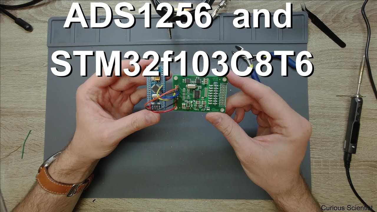
This video guides the connection of ATS 1256 port to STM32 microcontroller through detailed wiring and programming steps.
Transcript
welcome everyone in this video I'm going to show you how to connect the ATS 1256 port to an STM 32 microcontroller and the board that I'm going to work with can be seen under the magnifying glass so let me just move this away so this guy here which we are going to work with today and there is there are a few differences between this board and these... Read More
Key Insights
- 😴 The ATS 1256 port connection process is accessible through clear instructions and detailed pin configuration.
- 🏂 Understanding the differences between various boards is crucial for ensuring compatible wiring and successful operation.
- 😴 Proper handling of reset and sync pins is essential to maintain device performance and reliability.
- ✊ An independent power supply can enhance device functionality by minimizing potential disruptions.
- 🥺 Efficient soldering and wiring techniques lead to a more compact and organized circuit setup.
- 🏆 Testing the finalized circuit with a computer is a critical step to ensure all connections are functional.
- 💇 Aesthetics and functionality can be balanced by cutting excess wires and maintaining a neat design.
Install to Summarize YouTube Videos and Get Transcripts
Explore YouTube Video Summarizer or Get YouTube Transcript Extractor
Questions & Answers
Q: What are the main components required to connect the ATS 1256 to the STM32 microcontroller?
The essential components include the ATS 1256 port, STM32 microcontroller, appropriate wiring for power and communication, and a soldering iron for connections. Additionally, resistors may be used for the reset pin configuration, while an independent power supply can enhance reliability.
Q: Why is it important to handle the reset and sync pins correctly in this setup?
Handling the reset and sync pins is crucial because these pins control the operational modes of the ATS 1256. Connecting them to the correct power voltage ensures the device operates in its intended functional state without causing disruptions or resets during communication processes.
Q: How does pin layout differ across the boards mentioned in the video?
The primary difference among the boards lies in the presence or absence of certain digital pins. For example, while some boards include a PD WN pin, others may feature a reset pin. However, the functionality remains largely consistent, allowing for adaptable connections through similar wiring setups.
Q: What considerations should be made when selecting power sources for the ATS 1256?
When selecting power sources for the ATS 1256, it’s essential to consider current requirements, voltage levels, and device compatibility. Using an independent power supply can minimize interference, especially for sensitive devices, ensuring stable performance and reducing risks of data loss during readings.
Q: What steps did the presenter take after finishing the soldering process?
After completing soldering, the presenter cut off excess wire lengths for aesthetics and compactness. They then proceeded to connect the board to a computer for testing purposes, ensuring that all connections were secure and functional before finalizing assembly in a metal enclosure.
Q: How does the configuration of the power and communication pins affect the device's operation?
The configuration of power and communication pins directly impacts the device's ability to function effectively. Properly connecting these pins allows the microcontroller to send and receive data accurately, ensuring reliable communication with the ATS 1256, which is vital for operational success.
Q: What are the benefits of maintaining a compact design in this wiring setup?
Maintaining a compact design is beneficial as it minimizes the space required for the setup, reduces potential interference, and enhances portability. A tighter arrangement also simplifies troubleshooting and maintenance, allowing for easier access to connections without excessive clutter.
Q: Why might one consider using a metal enclosure for the completed circuit?
A metal enclosure is advisable for the completed circuit because it provides physical protection from environmental factors, prevents electromagnetic interference, and enhances the overall durability of the setup. This ensures that the internal components remain safe and functional over extended use.
Summary & Key Takeaways
-
The video demonstrates how to connect the ATS 1256 port with an STM32 microcontroller, highlighting the necessary pin configurations and differences between various boards.
-
Detailed instructions are provided on wiring the power and communication pins, including how to handle reset and sync pins, ensuring clarity and ease of understanding.
-
The presenter completes the soldering process and prepares the finalized circuit for testing, emphasizing the importance of compact design and maintaining power supply integrity.
Read in Other Languages (beta)
Share This Summary 📚
Summarize YouTube Videos and Get Video Transcripts with 1-Click
Try YouTube Summary with ChatGPT & Claude or YouTube Transcript Generator
Explore More Summaries from Curious Scientist 📚


![Building a Peltier cooler-based cooling box - First iteration, improvements [Part 2/6] thumbnail](/_next/image?url=https%3A%2F%2Fi.ytimg.com%2Fvi%2F0YlNw0EGnzI%2Fhqdefault.jpg&w=750&q=75)

Summarize YouTube Videos and Get Video Transcripts with 1-Click
Try YouTube Summary with ChatGPT & Claude or YouTube Transcript Generator