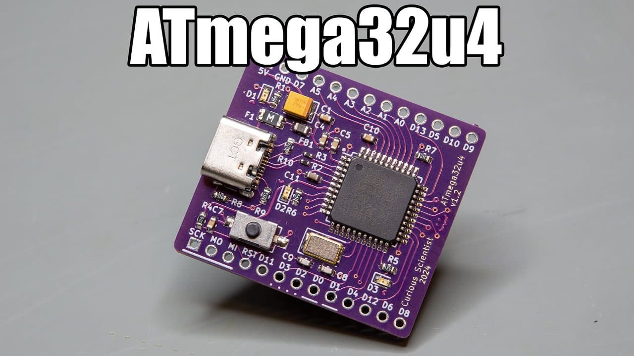
Custom ATmega32u4 microcontroller board - 2024 version
TL;DR
The video revisits and enhances a circuit board project using the ATmega32U4 microcontroller.
Transcript
this video is sponsored by pcbway welcome everyone in this video I'm going to revisit one of my earlier projects and I will give it a substantial facelift so earlier about 2 years ago I designed the circuit board based on the 0 Mega 32 u4 microcontroller and I'm going to revisit that board in this video it is a fun to use chip because it carries th... Read More
Key Insights
- 🎨 The project revisits an earlier design, emphasizing iterative improvement in electronic circuit design.
- 🎅 Adoption of USB-C reflects a shift towards modern standards in hardware, showcasing industry trends.
- 👻 Enhanced component placement allows for improved fit within breadboard configurations, making for practical prototyping.
- 👤 Clear labeling and design adjustments can lead to better user understanding, facilitating easier implementation and use of the board.
- 😀 Observations during the assembly process highlight critical challenges faced and how they can impact overall board functionality.
- 🏂 Testing steps taken post-assembly validate the integrity and performance of the circuit board, ensuring reliable operation.
- 🫵 The importance of maintaining documentation and links for community resources supports retesting and educational outreach for viewers.
Install to Summarize YouTube Videos and Get Transcripts
Explore YouTube Video Summarizer or Get YouTube Transcript Extractor
Questions & Answers
Q: What are the main improvements made to the ATmega32U4 circuit board?
The main improvements include a shift to a USB-C connector, narrower board design for breadboard compatibility, and clearer labeling of pin functions. These design updates are aimed at maintaining modern standards and enhancing usability for users, especially in DIY electronics projects.
Q: Why was the USB-C connector chosen over the older micro USB?
USB-C was chosen because it has become the standard connector type, providing better compatibility with contemporary devices. Additionally, swapping from micro USB to USB-C helps future-proof the board, as micro USB is gradually becoming obsolete in the market.
Q: How did the presenter address issues with the reflow process during assembly?
The presenter experienced challenges during the reflow process due to the hot plate’s rapid heating, which caused solder bolts to form. This was mitigated by cleaning up after the process, ensuring no short circuits or solder issues existed, confirming the board’s integrity afterward.
Q: What steps were taken to program the new ATmega32U4 board?
To program the new board, the presenter used an Arduino Nano as a programmer, uploading the Arduino ISP code first. By connecting SPI pins and selecting the appropriate settings in the Arduino IDE, they managed to burn a bootloader onto the ATmega32U4, allowing software uploads.
Q: How did the presenter ensure the board's functionality after assembly?
After assembling the board, the presenter used a USB tester to check for power consumption and verify there were no short circuits. Subsequent tests involved detecting the board in device manager and uploading a simple sketch to confirm that the microcontroller could successfully communicate via USB.
Q: What insights does the presenter share about design considerations for PCBs?
The presenter emphasizes the importance of component placement, trace thickness, and curve design for aesthetic appeal. Additionally, clear labeling of pins and functionalities greatly enhances usability and simplifies troubleshooting for users, which is crucial for those new to working with microcontrollers.
Summary & Key Takeaways
-
The presenter showcases significant improvements made to a previous ATmega32U4 circuit board, including a new USB-C connector and redesigned layouts for better fit and performance.
-
Key design changes include thinner curved traces and clearer labeling for pins and peripherals, enhancing user experience and understandability of the board's functions.
-
After assembling the new board successfully, the presenter demonstrates programming the board and testing its functionality, confirming that it operates as intended without electrical faults.
Read in Other Languages (beta)
Share This Summary 📚
Summarize YouTube Videos and Get Video Transcripts with 1-Click
Try YouTube Summary with ChatGPT & Claude or YouTube Transcript Generator
Explore More Summaries from Curious Scientist 📚
![Building a coil winder [Part 6] - A few improvements thumbnail](/_next/image?url=https%3A%2F%2Fi.ytimg.com%2Fvi%2F3eyxG_g2iUA%2Fhqdefault.jpg&w=750&q=75)


Summarize YouTube Videos and Get Video Transcripts with 1-Click
Try YouTube Summary with ChatGPT & Claude or YouTube Transcript Generator