How to Use Rotary Encoders with Custom DRO PCBs
TL;DR
To use rotary encoders with a custom DRO PCB, modify the existing circuit and update the software to read encoder signals accurately. The process includes integrating an ATtiny85 microcontroller, implementing necessary hardware changes, and coding adjustments to ensure precise display of position and RPM. This setup is adaptable for various machinery applications.
Transcript
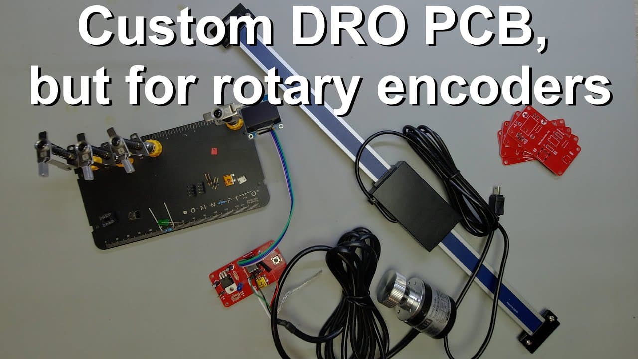
welcome everyone in this video i'm going to talk about a board which i have introduced before but now i'm going to show you another application of this board so this board might be already familiar to you if you have been following my channel for a while it's a very nice red pcb and i made this to make it possible to read the dros for example this ... Read More
Key Insights
- 🤤 The discussed board is versatile, enabling readings for a variety of mechanical systems using DROs and rotary encoders.
- 👶 Introducing a new encoder variant significantly improves the resolution and efficiency of the readings compared to traditional models.
- 😄 Practical soldering and assembly techniques are shared to aid viewers in replicating the board setup with ease.
- 👨💻 The programming aspect is simplified through a structured breakdown, showcasing adaptable coding for different microcontrollers.
- 🫵 By detailing changes to the existing code, viewers gain valuable skills to apply this knowledge to their projects.
- 👨💻 The system's response time and accuracy is enhanced through careful timing and interrupt handling in the code.
- 🐕🦺 The video asserts the value of utilizing PCB services, streamlining the production process for custom electronics projects.
Install to Summarize YouTube Videos and Get Transcripts
Explore YouTube Video Summarizer or Get YouTube Transcript Extractor
Questions & Answers
Q: What is the primary function of the board discussed in the video?
The primary function of the board is to read digital readouts (DROs) from devices like milling machines and display their positions on an OLED screen. It achieves this through a microcontroller that interprets encoder signals to deliver accurate readings for distance or displacement movements.
Q: How does the new rotary encoder improve the setup?
The new rotary encoder enhances the system by providing smoother operation with less mechanical resistance, allowing for accurate readings of angular displacement. Its design includes a 360 pulses-per-revolution (PPR) capability, which improves the resolution to one degree, making it suitable for precise measurements in various applications.
Q: What steps did the presenter take to implement the hardware modifications?
The presenter showcased a rebuild of the circuit from scratch, adding components such as jumper pins and an updated microcontroller socket. They detailed the soldering procedure for USB ports and other connections, ensuring the new rotary encoder could interface effectively with the existing board.
Q: Can you explain the coding changes required for the ATtiny85 microcontroller?
The coding changes involve adapting libraries specific to the ATtiny85, such as those for I2C communication and the OLED display. The presenter explains managing interrupts for real-time signal processing from the rotary encoder, while maintaining accuracy in reading the position and calculating RPM based on time intervals.
Q: Why is the display setup important in the circuit?
The display setup is crucial as it provides real-time feedback on both position and RPM values. This visual data allows users to monitor mechanical movements and speeds easily, enhancing the user experience when operating machinery linked to the system.
Q: What is the significance of having a tare button in the circuit?
The tare button allows users to reset the position to zero at any desired point, facilitating straightforward tracking of changes in displacement during operation. This functionality is essential in applications where precise measurements are necessary over consecutive movements.
Summary & Key Takeaways
-
The video demonstrates a board designed for reading digital readouts (DROs) and controlling displays using rotary encoders in machinery.
-
It explains modifications to implement a more effective encoder, detailing both hardware changes and software adjustments for accurate data processing and display.
-
Viewers learn step-by-step coding instructions for using an ATtiny85 microcontroller, alongside practical assembly tips for compatible circuit building.
Read in Other Languages (beta)
Share This Summary 📚
Summarize YouTube Videos and Get Video Transcripts with 1-Click
Try YouTube Summary with ChatGPT & Claude or YouTube Transcript Generator
Explore More Summaries from Curious Scientist 📚


![Building a coil winder [Part 6] - A few improvements thumbnail](/_next/image?url=https%3A%2F%2Fi.ytimg.com%2Fvi%2F3eyxG_g2iUA%2Fhqdefault.jpg&w=750&q=75)
![Building a Peltier cooler-based cooling box - First iteration, improvements [Part 2/6] thumbnail](/_next/image?url=https%3A%2F%2Fi.ytimg.com%2Fvi%2F0YlNw0EGnzI%2Fhqdefault.jpg&w=750&q=75)
Summarize YouTube Videos and Get Video Transcripts with 1-Click
Try YouTube Summary with ChatGPT & Claude or YouTube Transcript Generator