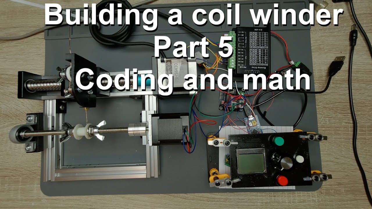
Building a coil winder [Part 5] - Coding and math
TL;DR
This video explains the theoretical aspects and programming for controlling stepper motors in a coil winding project.
Transcript
welcome everyone this is the fifth video of the coilbinder building series and this video will be entirely theoretical so i will be talking about the technical details the source code which is on the microcontroller and some of the calculations which are used to move the stepper motors especially the feeder in a proper way so this source code in fa... Read More
Key Insights
- 👻 Using a rotary encoder allows for precise control over motor direction and speed adjustments, crucial for effective coil winding.
- 👨💻 Source code optimization and variable management are fundamental in ensuring smooth communication between components and the microcontroller.
- 🎨 The theoretical calculations for wire length and steps highlight the complexity involved in designing a functional coil winder.
- ⚡ Appropriate voltage levels (3.3V) should be observed for sensitive components to maintain operational reliability.
- 👤 Debounce functions are critical in handling user inputs effectively, enhancing user experience during adjustments.
- 🧑🦼 The project creatively repurposes a previous universal stepper motor control panel, showcasing practical applications in electronics.
- 💁 By synchronizing feeder speed with the main shaft, the project minimizes the likelihood of operational errors during coil formation.
Install to Summarize YouTube Videos and Get Transcripts
Explore YouTube Video Summarizer or Get YouTube Transcript Extractor
Questions & Answers
Q: What microcontroller is used in this project, and why is it suitable for controlling stepper motors?
The specific microcontroller used is not mentioned; however, it must support SPI communication for connecting the Nokia 5110 display and handle multiple I/O pins for buttons and stepper motor drivers. The suitability lies in its ability to execute precise timing and implement complex algorithms for motor control, essential in applications like coil winding.
Q: How does the rotary encoder contribute to the operation of the coil winder?
The rotary encoder provides a means to monitor and adjust the position and speed of the stepper motors in real-time. It consists of pins that communicate the direction and the number of increments turned, allowing for smoother adjustments. This feedback loop enables accurate control of parameters like the feeder's speed and the number of turns for winding.
Q: Can you elaborate on the significance of the variable debounce mechanism described in the video?
The debounce mechanism is crucial for preventing false button presses from being registered when a button is pressed repeatedly in quick succession. It uses timers to ignore subsequent presses until the timer elapses, ensuring that each press is counted as a single action. This helps in maintaining stable and reliable operation during manual adjustments or selections in the menu.
Q: What calculations are involved in determining the length of wire used in the coil?
The calculations take into account the number of turns, wire diameter, bobbin width, and the increasing diameter of the coil as layers are added. It uses geometric formulas to account for the varying circumference as layers build, ensuring accurate tracking of wire consumption. This complexity ensures that the coil winding process results in the correct amount of wire being utilized.
Q: Why is it recommended to use 3.3V instead of 5V for powering the display?
Using 3.3V helps prevent potential damage to components integrated into the display, ensuring compatibility and longevity. While some sellers may claim 5V compatibility, operating at a lower voltage provides a safeguard against overvoltage issues, promoting stable performance and reducing the risk of overheating.
Q: How does the code handle the calculation of steps for both the main shaft and feeder?
The code calculates total steps based on user input values such as the number of turns and the microstepping configuration. It incorporates parameters like the wire diameter and bobbin width to ensure the feeder steps are synchronized with the main shaft operation, effectively coordinating movements for precise coil winding.
Q: What safety features are integrated into the design to prevent overheating of stepper motors?
There are multiple safety features, including disabling power to the stepper motors when not in motion and monitoring temperature feedback to adjust operations dynamically. These features help lower the risk of overheating, prolong the life of the motors, and increase reliability during extended winding operations.
Summary & Key Takeaways
-
The video focuses on the theoretical framework behind controlling stepper motors for a coil winding project, emphasizing the importance of source code functionality and variable management.
-
It discusses essential components including a Nokia 5110 display, rotary encoder, and control panel, detailing how they interact to facilitate the winding process and adjust parameters.
-
The speaker elaborates on calculations necessary for steering the stepper motors, ensuring efficiency and accuracy, while managing torque and speed settings to prevent overheating and improve performance.
Read in Other Languages (beta)
Share This Summary 📚
Summarize YouTube Videos and Get Video Transcripts with 1-Click
Try YouTube Summary with ChatGPT & Claude or YouTube Transcript Generator
Explore More Summaries from Curious Scientist 📚
![Building a Peltier cooler-based cooling box - First iteration, improvements [Part 2/6] thumbnail](/_next/image?url=https%3A%2F%2Fi.ytimg.com%2Fvi%2F0YlNw0EGnzI%2Fhqdefault.jpg&w=750&q=75)


Summarize YouTube Videos and Get Video Transcripts with 1-Click
Try YouTube Summary with ChatGPT & Claude or YouTube Transcript Generator