How to Control DC Motor Position Using PID Control
TL;DR
To control a DC motor's position using PID control, you need to implement a feedback loop that adjusts the motor based on the difference between the target position and actual position readings from a magnetic encoder. By programming an Arduino to manage the PWM signal and continuously calculate the error, you can achieve precise motor positioning for various applications.
Transcript
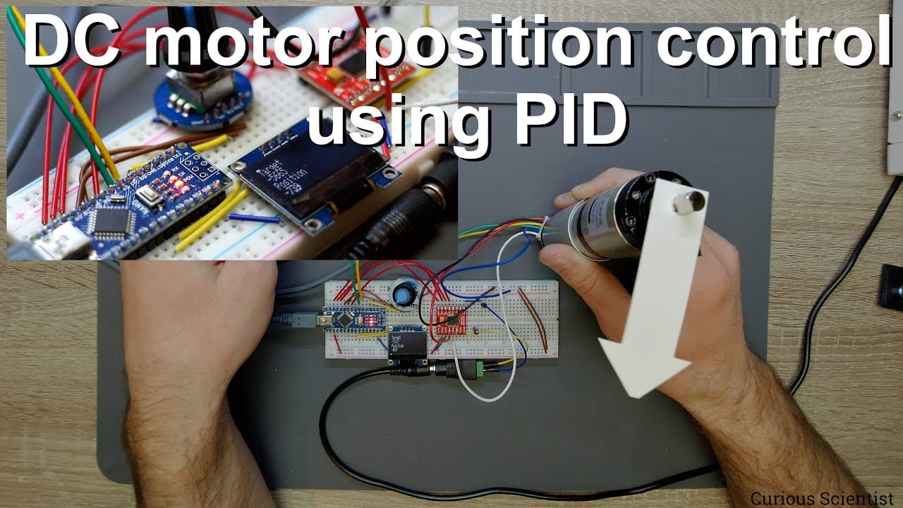
welcome everyone in this video i'm going to show you how to control a dc motor using a pid control and the pid control in this case will be based on the position of the shaft of the motor and what we will do is that we will read the position of the shaft based on the magnetic encoder attached to the main shaft as you can see it here and based on th... Read More
Key Insights
- 🎮 PID control is vital for precise motor control, allowing for real-time adjustments based on position feedback.
- 🖱️ The use of magnetic encoders translates physical rotations into measurable data for computing position accuracies.
- 🧑🦼 Geared motors can significantly enhance torque and position control when functioning with a magnetic encoder.
- 🧑🦼 Educating oneself on PID parameters can greatly improve the effectiveness of motor control applications.
- ❓ An effective display feedback mechanism can simplify monitoring the system's status and adjustments.
- 🧑🦼 The Arduino platform is accessible for implementing complex control algorithms in motor applications.
- ❓ The proper calibration of PID settings requires patience and systematic experimentation for optimal results.
Install to Summarize YouTube Videos and Get Transcripts
Explore YouTube Video Summarizer or Get YouTube Transcript Extractor
Questions & Answers
Q: What is the primary purpose of using PID control in this project?
The primary purpose of using PID control in this project is to achieve precise control of the motor's position. PID, which stands for Proportional-Integral-Derivative control, helps to minimize the difference between the desired set point (target position) and the actual position of the motor shaft, allowing for accurate adjustments in movement.
Q: How is the position of the motor shaft determined?
The position of the motor shaft is determined using a magnetic encoder attached to the motor's main shaft. This encoder generates specific pulses as the shaft rotates, which are read by the Arduino to calculate the current position of the shaft relative to the target position.
Q: What components are necessary for building this motor control system?
The necessary components include a DC motor, a geared system (such as a planetary gearbox), a magnetic encoder, an Arduino (e.g., Arduino Nano), a PWM motor driver (like the TB6612), a rotary encoder for setting target positions, and an OLED display for visual feedback on the target and current positions.
Q: Can the code and schematics for this project be accessed easily?
Yes, the code and schematics for this project can be accessed via the content creator's website, which provides all necessary resources, including details on how to set up the hardware and the programming required.
Q: What troubleshooting tips are provided for PID tuning?
For PID tuning, tip recommendations include experimenting with the PID parameters (proportional, integral, derivative) to observe their effects on motor performance, using online resources for guidance on parameter adjustments, and practicing systematic testing to find optimal settings for the specific motor and application.
Q: What benefits does a geared motor provide in this application?
A geared motor provides increased torque and control over the motor's speed and positioning, which is essential for applications requiring precision. The gearbox translates higher RPMs from the motor into controlled, lower RPMs at the output shaft, enhancing the system's capability to respond accurately to changes in target position.
Summary & Key Takeaways
-
The tutorial focuses on how to use PID control to precisely manage the position of a DC motor, aided by a magnetic encoder.
-
The setup includes an Arduino, a DC motor with a geared system, and components like a PWM motor driver and OLED display for monitoring.
-
The video also covers how to program the Arduino to read position values, compute errors, and adjust motor movement towards a set target position.
Read in Other Languages (beta)
Share This Summary 📚
Summarize YouTube Videos and Get Video Transcripts with 1-Click
Try YouTube Summary with ChatGPT & Claude or YouTube Transcript Generator
Explore More Summaries from Curious Scientist 📚


Summarize YouTube Videos and Get Video Transcripts with 1-Click
Try YouTube Summary with ChatGPT & Claude or YouTube Transcript Generator