How to Create a Simple Displacement Sensor with Arduino
TL;DR
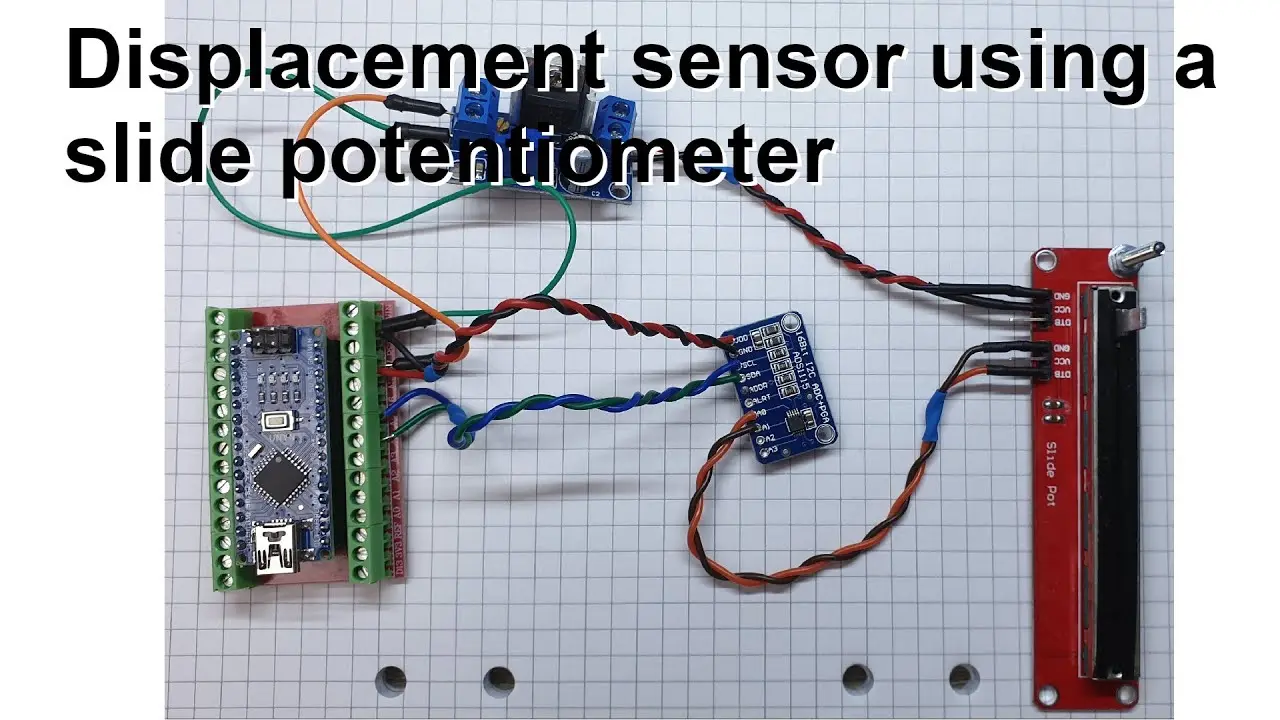
To create a simple displacement sensor using an Arduino, connect a sliding potentiometer to an ADC and a voltage regulator. This setup measures physical displacements by translating them into voltage changes, which the ADC reads for accurate distance calculations. Proper calibration and choosing the right components are essential for reliable measurements in applications like tensile testing.
Transcript
welcome everyone in this video I'm going to talk about a very simple displacement sensor I took a picture of the setup and I put it in an image editing software so it will be more easy to draw and write some things which are important so that's what you can see on the screen so let's jump into the parts so the main part of this is of course here th... Read More
Key Insights
- 🛝 The setup involves an Arduino Nano, LM317 voltage regulator, and sliding potentiometer for creating a simple displacement sensor.
- 🫠 The sensor translates physical displacement into voltage changes, which are read by an ADC via I2C for precise measurement.
- 📡 Ensuring effective signal resolution hinges on choosing the proper potentiometer alignment and ADC settings, enhancing data quality.
- 🌍 Calibration with known distances is essential for achieving accurate measurements, enabling real-world application reliability.
- 🚱 Non-linear behavior of certain potentiometers can complicate measurements, necessitating careful selection and calibration.
- 😒 The use of differential mode with the ADC enhances measurement accuracy by reducing electrical noise interference.
- 🥅 The device's ultimate goal is integration into a tensile testing machine for comprehensive material analysis.
Install to Summarize YouTube Videos and Get Transcripts
Explore YouTube Video Summarizer or Get YouTube Transcript Extractor
Questions & Answers
Q: What is the primary purpose of the Arduino in this displacement sensor setup?
The Arduino acts as the central control unit for the sensor setup, utilizing its I2C bus for communication with the ADC. It provides a 5V output, which is stepped down through a voltage regulator for the potentiometer, enabling precise voltage measurements that correspond to physical displacements.
Q: How does the voltage regulator contribute to the sensor's functionality?
The voltage regulator, specifically the LM317 T chip, reduces the Arduino's 5V output to around 2.05V, which is optimal for the linear potentiometer. This configuration allows for greater voltage variation detection over the potentiometer's range, improving measurement accuracy for small displacements.
Q: Why is it necessary to use a differential mode with the ADC?
Utilizing differential mode with the ADC improves precision in measurements by eliminating noise and ensuring a more accurate reading of voltage differences. By pairing channels, the setup effectively reduces errors, which is crucial in environments where electrical noise may affect the signal.
Q: What resolution can be achieved with the setup, and what factors influence it?
The setup theoretically achieves a resolution of about 18.3 micrometers, derived from dividing the potentiometer's measurement range into 32,768 steps. Factors such as the quality of the potentiometer and the effective range selected by the PGA settings can significantly influence actual resolution.
Q: What limitations are discussed concerning the potentiometer's characteristics?
The video highlights that the specific potentiometer used is logarithmic rather than linear, which complicates the relationship between slider position and output voltage. This non-linear response can lead to less intuitive readings at certain positions, particularly at the start and end of the potentiometer's travel.
Q: How does the video illustrate calibration for the displacement sensor?
Calibration is demonstrated by employing external tools like a caliper or ruler to correlate voltage readings to physical displacements accurately. The process involves establishing a direct mathematical relationship between the observed voltages from the potentiometer and corresponding distances, improving measurement reliability.
Q: What future applications are planned for this displacement sensor technology?
The creator plans to integrate this displacement sensor into a tensile testing machine to measure cross-head or grip displacements. This application aims to enhance the machine's functionality by enabling both displacement and force measurements for material testing.
Summary & Key Takeaways
-
The content discusses a displacement sensor setup using an Arduino Nano, a voltage regulator, and a linear potentiometer. This configuration allows for measuring small displacements through voltage changes.
-
The Arduino is connected to an ADC (Analog to Digital Converter), facilitating precise readings by using the I2C bus for data communication and enabling the potentiometer to function effectively within a specific voltage range.
-
The importance of calibrating the sensor for accuracy is detailed, alongside potential applications in tensile testing machines, showcasing the practicality of the setup in real-world scenarios.
Read in Other Languages (beta)
Share This Summary 📚
Summarize YouTube Videos and Get Video Transcripts with 1-Click
Try YouTube Summary with ChatGPT & Claude or YouTube Transcript Generator
Explore More Summaries from Curious Scientist 📚

![Building a coil winder [Part 6] - A few improvements thumbnail](/_next/image?url=https%3A%2F%2Fi.ytimg.com%2Fvi%2F3eyxG_g2iUA%2Fhqdefault.jpg&w=750&q=75)


Summarize YouTube Videos and Get Video Transcripts with 1-Click
Try YouTube Summary with ChatGPT & Claude or YouTube Transcript Generator