MCP41100 digital potentiometer with Arduino/STM32
TL;DR
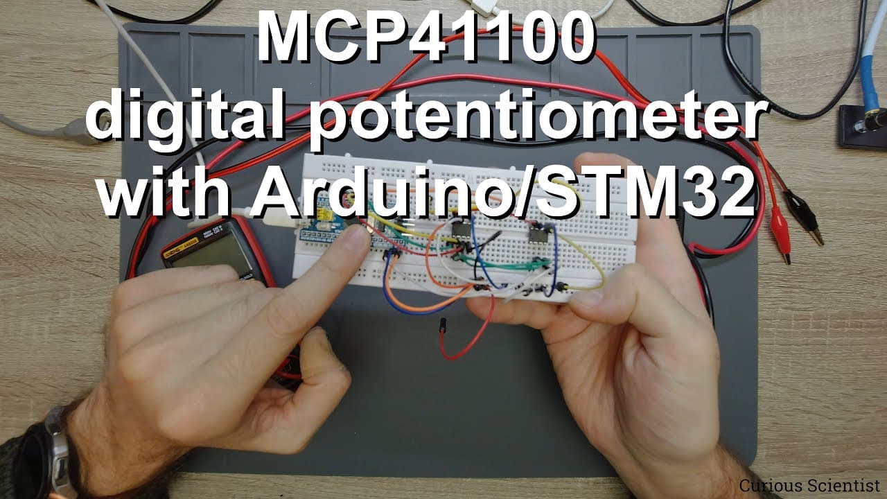
The video demonstrates using the MCP 41 100 digital potentiometer with STM32 for voltage control.
Transcript
welcome everyone in this video i'm going to show you a digital pod meter which is the mcp 41 100 potentiometer so as you can see i don't have too many things on the table right now so we have this breadboard here and now i'm using an stm32 circuit and we have one digital potentiometer here and the other is here and i will show you all the connectio... Read More
Key Insights
- 🦛 The MCP 41 100 is a digital pot providing SPI communication for adjusting voltage levels.
- 🐿️ Wiring is simplified with multiple chips connected in parallel, minimizing circuit complexity.
- ⌛ Effective voltage measurement can be achieved using standard multimeters to observe real-time adjustments.
- 👫 The presentation emphasizes practical applications, such as controlling LED brightness with dynamic resistance changes.
- ✊ Future projects intend to expand digital potentiometer applications, like creating a digital power supply with current regulation features.
- 🤩 An understanding of voltage dividers is key to grasping how potentiometers function in circuits.
- 🤩 Key mathematical relationships involved in resistance calculations are essential for understanding circuit behavior.
Install to Summarize YouTube Videos and Get Transcripts
Explore YouTube Video Summarizer or Get YouTube Transcript Extractor
Questions & Answers
Q: What is the purpose of the MCP 41 100 digital potentiometer?
The MCP 41 100 is a digital potentiometer that allows precise voltage adjustments using digital commands. By varying the resistance via an SPI interface, it facilitates control over voltage levels in electronic circuits, making it ideal for applications like brightness control in LED lighting.
Q: How does the STM32 microcontroller interact with the digital potentiometers?
The STM32 communicates with the MCP 41 100 using SPI protocol, where it sends commands to adjust the resistance. Each potentiometer has a dedicated chip select pin, allowing the microcontroller to access multiple digital pots on the same SPI bus without conflicts.
Q: Can you explain how the voltage measuring works in this setup?
In the setup, two multimeters measure the output voltage from each digital potentiometer. One pot decreases voltage from 3.3 volts to 0 volts while the other does the reverse, allowing real-time observation of how digital adjustments affect the voltage outputs displayed on the multimeters.
Q: What are the benefits of using digital potentiometers over analog ones?
Digital potentiometers offer more precise control as their adjustments can be made through digital signals. This allows for remote control and automation, better reproducibility, and integration with microcontrollers, making them more suitable for modern electronic applications.
Summary & Key Takeaways
-
The video covers the wiring and functionality of MCP 41 100 digital potentiometers connected to an STM32 microcontroller, highlighting the use of SPI communication.
-
It explains how these potentiometers adjust voltage levels from 3.3 volts to 0 volts, showcasing real-time changes displayed on multimeters.
-
Additionally, the presenter teases a future project focused on building a digital power supply that utilizes the concepts learned.
Read in Other Languages (beta)
Share This Summary 📚
Summarize YouTube Videos and Get Video Transcripts with 1-Click
Try YouTube Summary with ChatGPT & Claude or YouTube Transcript Generator
Explore More Summaries from Curious Scientist 📚


![Building a Peltier cooler-based cooling box - First iteration, improvements [Part 2/6] thumbnail](/_next/image?url=https%3A%2F%2Fi.ytimg.com%2Fvi%2F0YlNw0EGnzI%2Fhqdefault.jpg&w=750&q=75)

Summarize YouTube Videos and Get Video Transcripts with 1-Click
Try YouTube Summary with ChatGPT & Claude or YouTube Transcript Generator