Multiple stepper motors with joystick, TB6600 and the accelstepper library
TL;DR
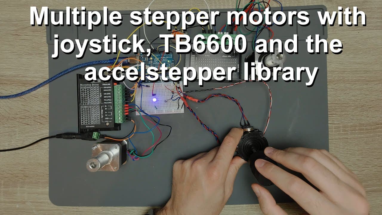
This video demonstrates how to control stepper motors using an Arduino and a joystick.
Transcript
welcome everyone in this video i'm going to continue the work with the joystick and arduino and stepper motors so as you can see i have a huge chaos on my table right now so we have two stepper motors these are sort of nema 17 stepper motors and i'm using the tb6600 drivers in fact i'm using two different drivers in the sense that i guess they come... Read More
Key Insights
- 🧑🦼 A three-axis joystick offers fine control for two stepper motors, enhancing precision in various applications.
- ⚾ Properly distinguishing between different TB6600 driver models helps in understanding potential performance variations based on manufacturing differences.
- 😴 Arduino's analog pins are crucial for capturing joystick input, converting analog voltages into digital signals for processing.
- 🧑🦼 It's essential to wire stepper motors correctly to avoid common issues such as incorrect motor rotation direction.
- 👫 LED responsiveness to joystick movements serves as both a demonstration of control and an engaging visual element.
- 🧑🦼 Average readings from potentiometers assist in eliminating jitter and ensuring smooth motor operation.
- 🧑🦼 The integration of multiple components presents opportunities for creating complex systems that could involve additional motors.
Install to Summarize YouTube Videos and Get Transcripts
Explore YouTube Video Summarizer or Get YouTube Transcript Extractor
Questions & Answers
Q: What components are used in the setup for controlling the stepper motors?
The setup uses two NEMA 17 stepper motors powered by TB6600 drivers, a three-axis joystick, and an Arduino Uno. The joystick has potentiometers that measure its position, and the microcontroller interprets these readings to control the motors.
Q: How is the wiring for the TB6600 stepper motor driver structured?
The wiring includes connections for power supply, ground, and motor signals. The TB6600 has specific ports for direction, enable, and pulse signals, which must be connected correctly to the Arduino for proper functioning.
Q: Can the motor rotation direction be easily changed?
Yes, the rotation direction can be flipped in the code. If the polarity is reversed while connecting the stepper motor wires, the direction can still be adjusted within the software to ensure correct movement as intended.
Q: How does the joystick affect the speed and direction of the motors?
The joystick alters the voltage output from its potentiometers. This voltage is read by the Arduino, which calculates both the speed and rotation direction of the motors based on how far the joystick is moved from its neutral position.
Q: What troubleshooting advice is given for noise in the joystick signal?
To reduce noise, the video suggests averaging the values from the potentiometers when initializing to filter out minor fluctuations in input due to electrical interference or varying power supply voltage conditions.
Q: What LED features are incorporated into the project?
An LED is connected to one of the PWM pins on the Arduino, allowing its brightness to be adjusted based on the third axis of the joystick. This provides a visual feedback element regarding the joystick's position.
Q: How do you determine wiring polarity for the stepper motor?
Wiring polarity can be confirmed using a multimeter on continuity mode. By connecting pairs of wires, you can determine which wires correspond to each phase of the stepper motor, ensuring correct wiring for operation.
Summary & Key Takeaways
-
The video focuses on interfacing a joystick with Arduino to control two stepper motors. The setup includes a three-axis joystick that changes the motors' speed and direction based on its position.
-
Detailed wiring of the TB6600 controller with the stepper motors and Arduino is explained, emphasizing polarity and signal connections for effective operation.
-
The coding part illustrates how joystick movements translate into motor control signals, showing the use of PWM for brightness adjustment on an LED connected to the Arduino.
Read in Other Languages (beta)
Share This Summary 📚
Summarize YouTube Videos and Get Video Transcripts with 1-Click
Try YouTube Summary with ChatGPT & Claude or YouTube Transcript Generator
Explore More Summaries from Curious Scientist 📚
![Building a Peltier cooler-based cooling box - First iteration, improvements [Part 2/6] thumbnail](/_next/image?url=https%3A%2F%2Fi.ytimg.com%2Fvi%2F0YlNw0EGnzI%2Fhqdefault.jpg&w=750&q=75)


Summarize YouTube Videos and Get Video Transcripts with 1-Click
Try YouTube Summary with ChatGPT & Claude or YouTube Transcript Generator