Tutorial: Op-amp circuit for force sensor signal conditioning
TL;DR
Learn how to create a circuit using an op-amp to measure the conductance of a force sensor and interface it with a microcontroller.
Transcript
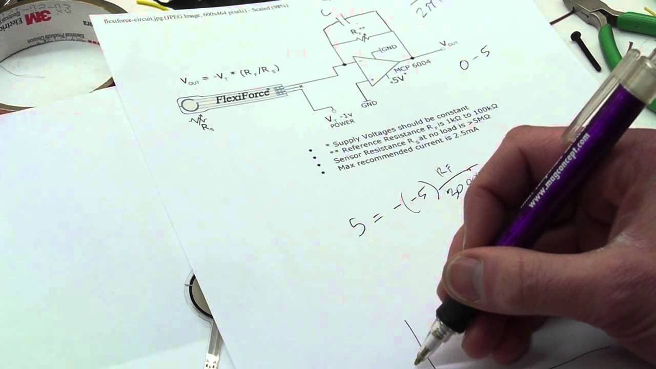
hey everyone in this video I'm going to show you a circuit that you can use to interface this force sensor with a microcontroller or some other analog input device so this is a flexi force a 4:01 force sensor and it's a sort of like a variable resistor so let me zoom in and show you how to how to make this circuit okay so this force sensor is built... Read More
Key Insights
- 🪡 The force sensor has a non-linear resistance curve, and a circuit is needed to compensate for this to obtain accurate force measurements.
- 💄 The conductance of the force sensor is linearly related to the applied force, making it a suitable parameter to measure.
- 🍾 An op-amp circuit with a feedback resistor is used to measure the conductance of the force sensor.
- 🍾 The circuit requires a negative voltage supply for the op-amp, which can be generated using a self-contained DC to DC converter.
- 😘 Low-pass filters can be added to the circuit to filter out unwanted AC noise.
- 🍾 The LM324 op-amp is used in the circuit due to its ability to provide a 0 to 5-volt output range and availability in various packages.
Install to Summarize YouTube Videos and Get Transcripts
Explore YouTube Video Summarizer or Get YouTube Transcript Extractor
Questions & Answers
Q: How does the resistance of the force sensor change with applied force?
The resistance of the force sensor decreases when force is applied, forming a curve that is non-linear.
Q: How does the circuit compensate for the non-linear curve of the force sensor?
The circuit uses the conductance of the force sensor, which is the reciprocal of resistance, to get a linear relationship with the applied force.
Q: What is the purpose of using an op-amp in the circuit?
The op-amp is used as a non-inverting amplifier to measure the conductance of the force sensor. It amplifies the signal and provides a linear output.
Q: How is the negative voltage supply for the op-amp generated?
A self-contained DC to DC converter is used to generate a negative 5-volt supply for the op-amp.
Summary & Key Takeaways
-
The video explains how to create a circuit using an op-amp to interface a force sensor with a microcontroller or analog input device.
-
The force sensor is a flexi force sensor with a variable resistance that changes with applied force.
-
The video demonstrates how to compensate for the non-linear resistance curve of the force sensor to obtain meaningful force measurements.
-
The circuit uses an op-amp and a feedback resistor to measure the conductance of the force sensor, which is linearly related to the applied force.
Read in Other Languages (beta)
Share This Summary 📚
Summarize YouTube Videos and Get Video Transcripts with 1-Click
Try YouTube Summary with ChatGPT & Claude or YouTube Transcript Generator
Explore More Summaries from Applied Science 📚




Summarize YouTube Videos and Get Video Transcripts with 1-Click
Try YouTube Summary with ChatGPT & Claude or YouTube Transcript Generator