Comparing 5 different ADS1256 boards and discussing some issues
TL;DR
The video clarifies the configurations and connections of various ATS 1256 boards and SPI communication.
Transcript
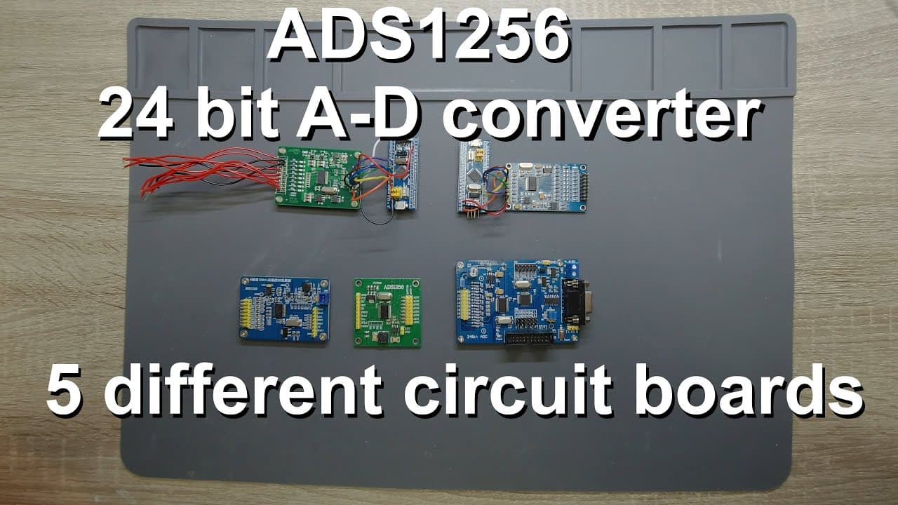
welcome Aaron there have been some confusions among these boards in the comment section as I could see so I decided to talk about the ATS 1256 boards again and as you can see now I have a pretty large collection of the different boards so in numbers this is actually five so I have five different boards as you can see some of them are already attach... Read More
Key Insights
- 🏂 The ATS 1256 boards each possess unique characteristics but share common functionalities like SPI protocol compatibility.
- 😴 The SPI communication setup requires attention to specific pins, which are consistent across different boards.
- 🏂 Data ready signals are crucial for effective timing in data acquisition from the ATS 1256 boards.
- 🏂 Understanding board specifications and datasheets is essential for successful integration with microcontrollers.
- ✊ Hardware reset and power-down mechanisms can be vital for preventing unwanted operational states.
- 🏂 Various applications can stem from these boards, particularly in sensor and data acquisition projects.
- 👾 A compact design for the integrated microcontroller helps streamline connections and reduce space requirements.
Install to Summarize YouTube Videos and Get Transcripts
Explore YouTube Video Summarizer or Get YouTube Transcript Extractor
Questions & Answers
Q: What are the critical differences between the ATS 1256 boards presented?
The main differences between the ATS 1256 boards are their pin configurations and the presence of certain functionalities like the reset pin and the sink or power-down pins. Some boards have an integrated microcontroller while others require separate connections. Understanding these variations is crucial for proper implementation.
Q: How do the SPI pins relate to the ATS 1256 boards?
All ATS 1256 boards utilize the SPI protocol, which necessitates four specific pins: clock (SCK), chip select (CS), master out/slave in (MOSI), and master in/slave out (MISO). These pins are essential for communication between the microcontroller and the boards, irrespective of the specific board being used.
Q: Why is the data ready pin important in ATS 1256 boards?
The data ready pin indicates when data is available from the ATS 1256, signaling to the microcontroller that it can read the output. Understanding how this pin functions helps ensure correct timing in data retrieval, which is crucial for reliable performance in applications like sensor data measurement.
Q: What applications can be developed using the ATS 1256 boards?
The ATS 1256 boards can be employed in various applications, including precise measurements with strain gauges. These boards enable the detection of small voltage changes linked to strain, facilitating projects that require accurate data logging and conversion of analog signals.
Q: What safety measures should be considered when connecting the reset and sink pins?
When connecting reset and sink pins, it's recommended to pull them high to avoid unintentional resets or malfunction. Using a safe voltage, such as 3.3 volts, ensures compatibility and prevents damage to the device. It's essential to consult datasheets for specific voltage compatibility before making connections.
Q: How significant are the provided examples from earlier projects in this video?
The examples from earlier projects are significant as they provide practical insights into using the ATS 1256 boards effectively. They illustrate real-world applications and coding related to the SPI protocol, assisting viewers in visualizing how to implement similar setups in their projects.
Summary & Key Takeaways
-
The presenter discusses five different ATS 1256 boards, highlighting unique features and configurations relevant for microcontroller connectivity, particularly regarding pin assignments.
-
A significant focus is placed on the common SPI protocol across the boards, emphasizing the necessary pins for connection, such as clock and data pins.
-
The video concludes with an introduction to an application involving strain gauges and an ADC setup, underscoring the necessity of understanding the datasheet for effective use.
Read in Other Languages (beta)
Share This Summary 📚
Summarize YouTube Videos and Get Video Transcripts with 1-Click
Try YouTube Summary with ChatGPT & Claude or YouTube Transcript Generator
Explore More Summaries from Curious Scientist 📚


Summarize YouTube Videos and Get Video Transcripts with 1-Click
Try YouTube Summary with ChatGPT & Claude or YouTube Transcript Generator