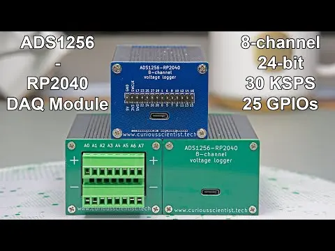
ADS1256-RP2040 GPIO Front Panel - Finished!

TL;DR
The video demonstrates completing a PCB project with ADS1256 module connections and coding for display output.
Transcript
this video is sponsored by pcbway welcome everyone in this video I'm going to finish this uh project with the front panel and the ads1256 module so I finally got the proper pre-crimped cables these guys here so now I have the chance to finish this uh thing properly uh previously I attempted to uh crimp the cables manually but as you can see these a... Read More
Key Insights
- 😑 The use of pre-crimped cables can significantly streamline the assembly process, especially with small connectors.
- 📽️ Accurate soldering and wiring are critical for ensuring reliable performance in electronic projects, as demonstrated through the project’s completion.
- ⚡ Understanding the functionality of the ADS1256 module is essential for effective voltage measurement and representation on connected displays.
- 🦻 Clear documentation, such as videos and project pages, aids in educating and guiding others through complex electronic builds.
- 👨💻 Access to libraries and example codes can expedite the learning process, making it easier for beginners to engage with electronics.
- 👻 Assembly services can benefit those lacking soldering skills, allowing for professional-level results without extensive personal expertise.
- 🎵 Consistent calibration and testing of electronic components are vital for accurate measurements, as noted in the comparisons between readings from the ADS1256 and a multimeter.
Install to Summarize YouTube Videos and Get Transcripts
Explore YouTube Video Summarizer or Get YouTube Transcript Extractor
Questions & Answers
Q: What issues did the presenter face with manual crimping?
The presenter encountered difficulties due to the tiny connectors involved in the project. Previous attempts to crimp the cables manually proved unsuccessful, which prompted the use of pre-crimped cables to ensure a proper fit and secure connections.
Q: How are the voltage readings displayed in the project?
The voltage readings are output on a small I2C LCD connected to the microcontroller. The device takes readings from the ADS1256 module, which processes the inputs from various channels and formats the data for display, allowing for real-time feedback during the experiment.
Q: What coding adjustments did the presenter make for the display?
The presenter adjusted the example code to accommodate the specific pins used for I2C communication in the project. These adjustments included defining SDA and SCL pins and implementing a function to convert digital values into voltage readings, which are then displayed correctly.
Q: What should viewers do if they want to replicate the project?
Viewers interested in replicating the project should refer to the presenter’s GitHub for the necessary code and libraries. They can also check the PCBway project page linked in the description for PCBs and assembly services, providing a comprehensive resource for similar projects.
Summary & Key Takeaways
-
The video outlines the final steps in completing a PCB project utilizing the ADS1256 module, including proper wire connections and display setup.
-
The presenter discusses challenges faced with manual crimping and demonstrates the use of pre-crimped cables to simplify assembly and ensure reliable connections.
-
A demonstration showcases the system’s functionality, with the display outputting voltage readings, emphasizing the importance of accurate wiring and coding in electronics projects.
Read in Other Languages (beta)
Share This Summary 📚
Summarize YouTube Videos and Get Video Transcripts with 1-Click
Try YouTube Summary with ChatGPT & Claude or YouTube Transcript Generator
Explore More Summaries from Curious Scientist 📚


Summarize YouTube Videos and Get Video Transcripts with 1-Click
Try YouTube Summary with ChatGPT & Claude or YouTube Transcript Generator