Debounced rotary encoder module
TL;DR
The video details a DIY rotary encoder PCB design, assembly, and evaluation process.
Transcript
this video is sponsored by pcbway welcome everyone in this video I'm going to show you my new little project it will be based on these small uh pcbs you can see that uh these are double-sided pcbs so both sides will be populated by components and uh this project is about a rotary encoder uh PCB so if you have been following me for a while uh you co... Read More
Key Insights
- 🥺 Customizing a PCB for a rotary encoder can lead to improved performance and reliability in electronics projects.
- 👻 Incorporating a Schmitt trigger allows for better signal clarity by eliminating noise associated with mechanical contact bouncing.
- 🫵 The video guides viewers through the entire process, from designing to assembling and testing the rotary encoder PCB.
- 📡 Detailed oscilloscope measurements highlight the importance of signal quality in embedded systems and microcontroller applications.
- 🅰️ The creator experiments with different types of rotary encoders, showcasing the variability in quality and performance among them.
- 🔬 Use of a microscope for assembly tasks underlines the intricate nature of electronic component handling and soldering.
- 🐕🦺 The sponsorship by PCB Way emphasizes the importance of reliable PCB manufacturing services for DIY electronics projects.
Install to Summarize YouTube Videos and Get Transcripts
Explore YouTube Video Summarizer or Get YouTube Transcript Extractor
Questions & Answers
Q: What motivated the creator to design their own rotary encoder PCB?
The creator aimed to build a custom rotary encoder module for enhanced long-term reliability and quality compared to cheaper, mass-produced options. While acknowledging that their design might not compete on price, they prioritize durability, especially for demanding projects that require consistent performance over time.
Q: What components are included on the custom rotary encoder PCB?
The PCB incorporates several components, including a rotary encoder, pull-up resistors, capacitors for filtering, and a Schmitt trigger IC. These components work together to ensure the output signals from the encoder are processed effectively, filtering out noise and producing clean signals for use in microcontroller applications.
Q: How does the Schmitt trigger improve the signals from the rotary encoder?
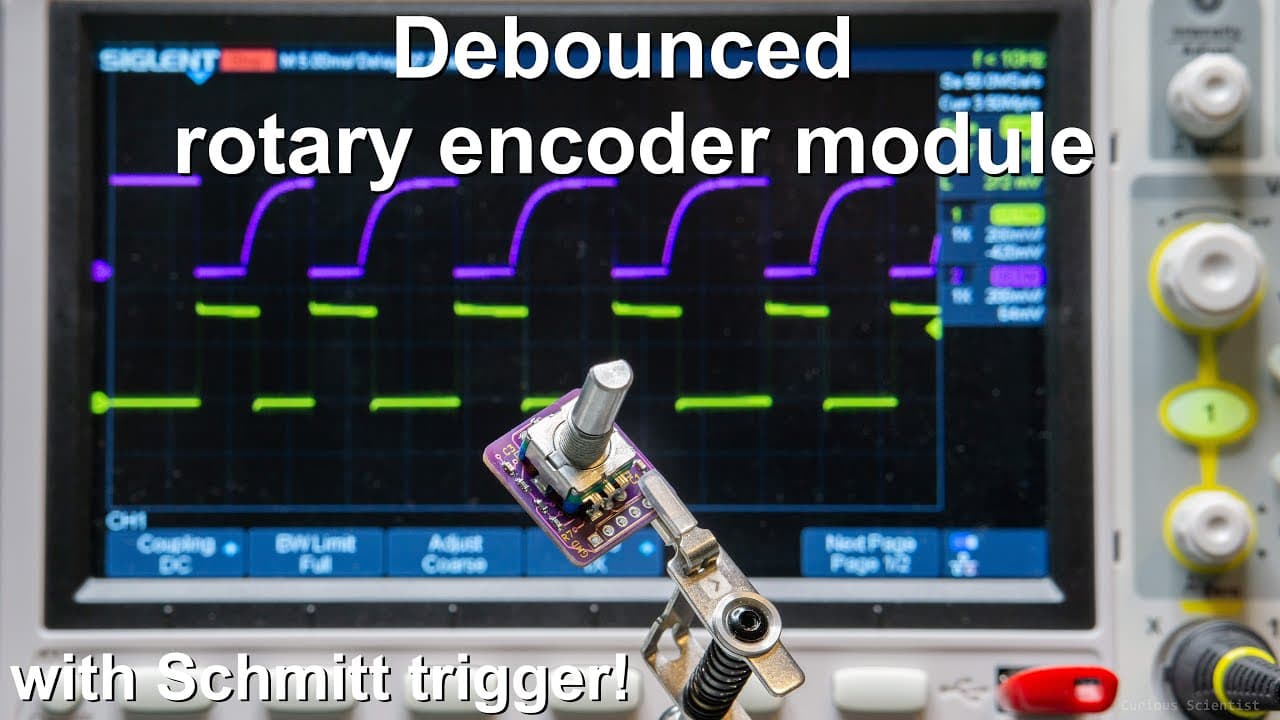
The Schmitt trigger inverts and shapes the signals from the rotary encoder, resulting in well-defined square wave outputs. This is critical as it smooths out the "bouncing" effect that can occur when contacts make and break, ensuring that the microcontroller receives clear, stable signals for reliable operation in various applications.
Q: What were the initial tests performed on the rotary encoder outputs?
Initial tests involved connecting the rotary encoders to an oscilloscope to analyze the output signals as the encoder was rotated in both directions. The goal was to observe the timing and quality of the resulting pulses, resulting in a visual demonstration of how the signals behave and the effectiveness of the filtering and processing being applied.
Q: Why is a microscope used during the assembly process of the PCB?
A microscope is utilized for the assembly of the PCB due to the small size of the components involved. This level of magnification allows for precise soldering and placement, ensuring that all connections are accurate and secure, which is especially vital for the functionality of the rotary encoder design.
Q: Where can viewers find the resources related to this project?
The creator encourages viewers to visit their website, where they have shared detailed resources, including the design files, materials, and components needed to reproduce the project themselves. Additionally, they provide links to PCB Way, where enthusiasts can have their PCB manufactured.
Summary & Key Takeaways
-
The project focuses on designing a custom rotary encoder PCB to enhance reliability compared to off-the-shelf options, while potentially improving long-term quality.
-
The video includes the assembly process of the PCB under a microscope, showcasing components like capacitors, resistors, and a Schmitt trigger IC for noise filtering.
-
The output signals from the rotary encoders are evaluated using an oscilloscope, demonstrating the effectiveness of the Schmitt trigger in producing clean square wave signals.
Read in Other Languages (beta)
Share This Summary 📚
Summarize YouTube Videos and Get Video Transcripts with 1-Click
Try YouTube Summary with ChatGPT & Claude or YouTube Transcript Generator
Explore More Summaries from Curious Scientist 📚

![Building a coil winder [Part 6] - A few improvements thumbnail](/_next/image?url=https%3A%2F%2Fi.ytimg.com%2Fvi%2F3eyxG_g2iUA%2Fhqdefault.jpg&w=750&q=75)


Summarize YouTube Videos and Get Video Transcripts with 1-Click
Try YouTube Summary with ChatGPT & Claude or YouTube Transcript Generator