OR gate | Realization using Diode and transistor | PDC | Lec-93
TL;DR
This video explains how to construct OR gates using diodes and transistors.
Transcript
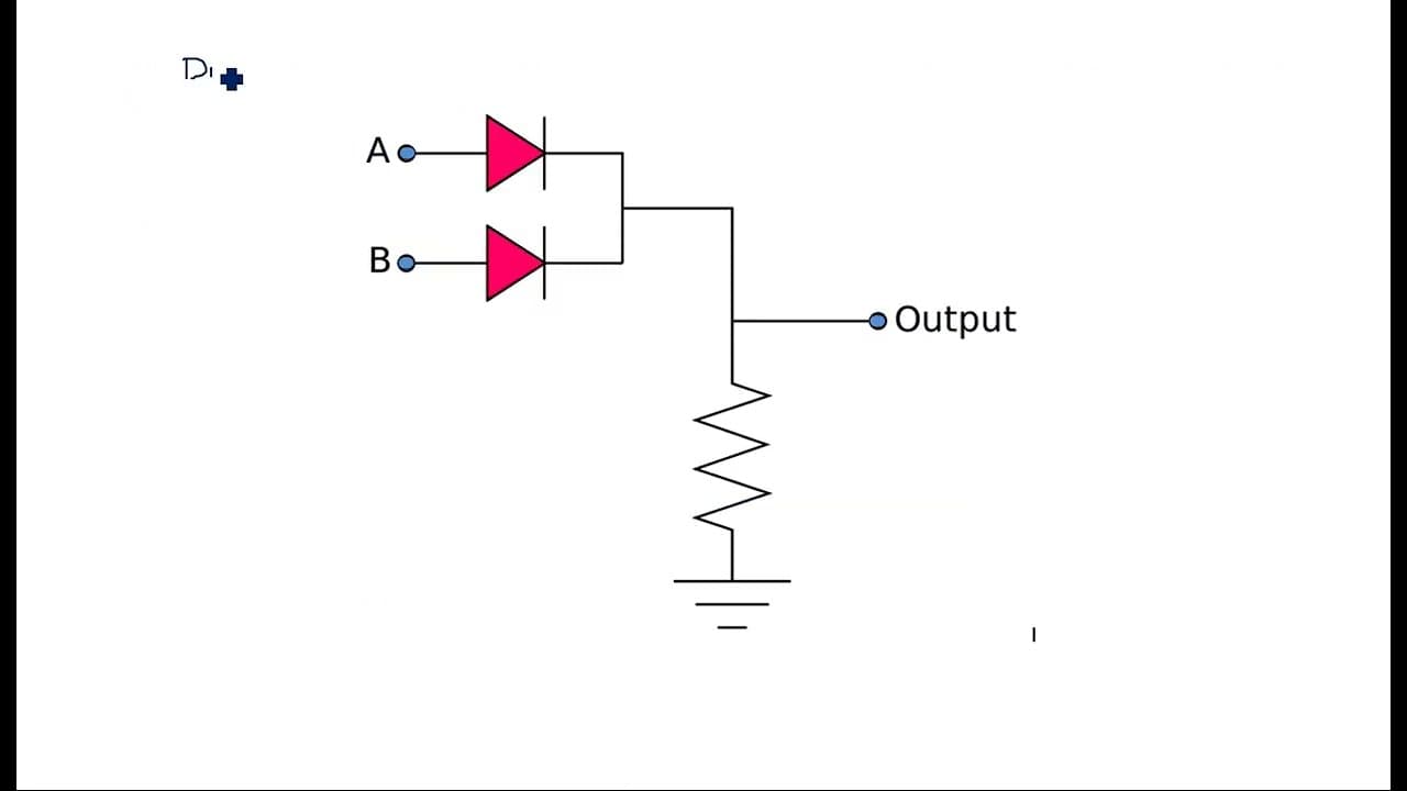
hi everyone in this video I am going to explain about the realization of or Gates using diodes and transistors here the logic gates like or gate and gate and any type of gate can be designed using the discrete components like diodes or transistors okay diode alone cannot act diode and with help of diode and resistor or transistor and resistor we ca... Read More
Key Insights
- 🔬 Discrete components, particularly diodes and transistors, are essential for creating digital logic gates like the OR gate.
- 🪡 Diode logic involves using multiple diodes in parallel to achieve OR gate functionality, highlighting the need for combined components for effective operation.
- 🎨 Resistor-transistor logic (RTL) utilizes a combination of resistors and transistors to realize logic gates, demonstrating versatility in digital circuit design.
- 💐 The operation of the OR gate relies heavily on controlling the current flow based on input states, confirming the logic conditions required for its function.
- ⚡ A minimum voltage differential is requisite for both diodes and transistors to operate effectively, underscoring the importance of voltage levels in electronic designs.
- 🫵 The concepts of logical gates are fundamental to understanding digital electronics, with truth tables providing a clear view of how inputs correlate to outputs.
- 🎨 Feedback mechanisms in transistor logic can modify outputs, indicating the complexity and design intricacies involved in advanced logic gate circuits.
Install to Summarize YouTube Videos and Get Transcripts
Explore YouTube Video Summarizer or Get YouTube Transcript Extractor
Questions & Answers
Q: Why can’t a diode function effectively on its own for designing logic gates?
Diodes require a complementary component, such as a resistor, to function properly in a logic gate design. A diode alone lacks the ability to manage the flow of current effectively for logical operations, resulting in unreliable outputs. When combined with a resistor, it can appropriately direct current flow based on input signals, enabling the formation of logic gates.
Q: How does a resistor-transistor logic (RTL) circuit implement an OR gate?
In an RTL OR gate circuit, multiple transistors are used along with resistors to determine output based on the input voltages. Each transistor acts as a switch that responds to input levels, controlling output via a third transistor to ensure the correct output state. If either input is high, the configuration allows current to flow, producing a high output.
Q: What role do diodes play in the construction of an OR gate?
Diodes in an OR gate configuration are responsible for allowing current to pass through when biased correctly, based on input voltage levels. By arranging the diodes in parallel and connecting their inputs to various switches, the gate can effectively produce a high output when at least one input is high, demonstrating its logical function.
Q: Can you explain the truth table for an OR gate?
The truth table for an OR gate outlines the output behavior based on two inputs, A and B. If both inputs are low (0), the output is low (0). If either input is high (1), the output turns high (1), and if both inputs are high, the output remains high. This illustrates the fundamental operation of the OR gate in digital logic.
Summary & Key Takeaways
-
The video discusses the fundamental design of OR gates employing discrete components such as diodes and transistors, emphasizing that diodes alone cannot function without resistors.
-
It provides a comprehensive guide to different configurations, including diode logic and resistor-transistor logic (RTL) for constructing OR gates, and explains how they operate based on input voltage levels.
-
The content also includes truth tables for the OR gate, detailing the expected outputs for various combinations of input states, reinforcing the fundamental principles of digital logic design.
Read in Other Languages (beta)
Share This Summary 📚
Summarize YouTube Videos and Get Video Transcripts with 1-Click
Try YouTube Summary with ChatGPT & Claude or YouTube Transcript Generator
Summarize YouTube Videos and Get Video Transcripts with 1-Click
Try YouTube Summary with ChatGPT & Claude or YouTube Transcript Generator