RLC Circuits (3 of 19) Resistance; Phase Shift, Phasor Diagrams, Impedance, An Explanation
TL;DR
Exploring pure resistive circuits in AC with phase shift, phasor diagrams, impedance, and voltage-current relations.
Transcript
okay today's video is until AC resistance and appiied is part 1 in this diagram I'm going to go over phase shift phasor diagrams and impedance for pure resistive circuits okay this is the basic circuit diagram that we have we have a resistor and a voltage source we have only resisted resistor and an AC voltage source so we have a resistive or a pur... Read More
Key Insights
- 🔙 Pure resistive circuits contain only resistors and AC sources, simplifying analysis.
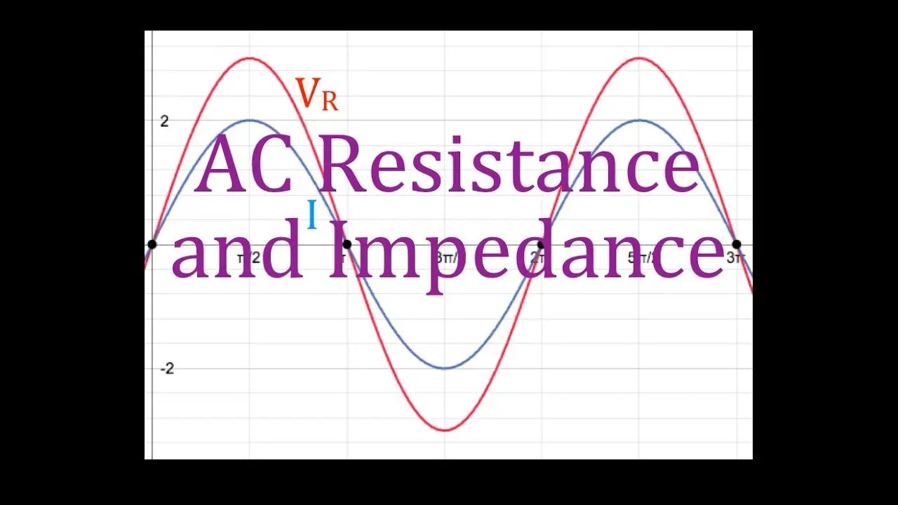
- 🥺 Voltage and current in pure resistive circuits are in phase, leading to simpler calculations.
- ⚡ Phasor diagrams visually represent the relationship between voltage and current.
- 💤 Impedance in AC circuits, denoted by Z, replaces resistance in DC circuits.
- 🙊 Peak current and voltage values in AC circuits are related through impedance.
- 👮 Ohm's law governs the relationships between voltage, current, and impedance in AC circuits.
- ❓ Impedance introduces a more complex analysis compared to resistance in DC circuits.
Install to Summarize YouTube Videos and Get Transcripts
Explore YouTube Video Summarizer or Get YouTube Transcript Extractor
Questions & Answers
Q: What is unique about pure resistive circuits in AC compared to inductive and capacitive circuits?
Pure resistive circuits consist only of resistors and AC sources, with voltage and current in phase, simplifying the analysis compared to circuits with inductors or capacitors.
Q: How are voltage and current represented in a phasor diagram for a pure resistive circuit?
In a phasor diagram for a pure resistive circuit, the peak current and voltage vectors are aligned with no phase shift between them, reflecting their in-phase relationship.
Q: What is the distinction between resistance in DC circuits and impedance in AC circuits?
Resistance (R) in DC circuits is replaced by impedance (Z) in AC circuits, where Z still follows Ohm's law but considers the complex nature of AC current flow.
Q: How does impedance affect the calculation of current in an AC circuit?
Impedance (Z) in AC circuits affects the calculation of current, where current (I) is determined as the ratio of voltage to impedance, replacing the direct proportionality seen in DC circuits.
Summary & Key Takeaways
-
Pure resistive circuits contain only resistors and AC voltage sources, with voltage and current in phase.
-
Phasor diagrams illustrate the relationship between voltage and current in resistive circuits.
-
Impedance in AC circuits differs from resistance in DC circuits due to the introduction of impedance Z instead of resistance R.
Read in Other Languages (beta)
Share This Summary 📚
Summarize YouTube Videos and Get Video Transcripts with 1-Click
Try YouTube Summary with ChatGPT & Claude or YouTube Transcript Generator
Explore More Summaries from Step by Step Science 📚


Summarize YouTube Videos and Get Video Transcripts with 1-Click
Try YouTube Summary with ChatGPT & Claude or YouTube Transcript Generator