How Do Logic Gates Function with Pulsed Waveforms?
TL;DR
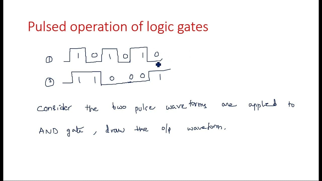
Logic gates can be analyzed using pulsed waveforms to determine output behavior without relying solely on truth tables. The output of AND, OR, and NOT gates can be derived from the timing and transitions of input waveforms, demonstrating how different input combinations affect the output state.
Transcript
hi everyone in this video I'm going to explain about the pulsed operation of logic GES actually this concept is very easy to understand just instead of taking the truth table every time by seeing the waveforms itself we can also draw the output waveform sometimes you are not asked to draw the you not you not asked to show the output values like one... Read More
Key Insights
- 👻 Pulsed operation allows visualization of logic gate outputs without solely relying on truth tables, making it intuitive for learners.
- 🔬 Proper identification of transition timings in the input waveforms is essential for accurately determining the output of logic gates.
- ✋ The AND gate requires simultaneous high inputs for producing a high output, reflecting logical AND conditions.
- 🔠 The OR gate outputs high whenever at least one input is high, accommodating cases with varying input states.
- 🔬 NOT gates only require one input, making their operation straightforward, contrasting with multi-input gates.
- 💗 Truth tables are crucial for establishing the logical functionality of gates and validating outputs derived from pulsed waveforms.
- 🔬 Multi-input gates, like a three-input AND gate, leverage multiple waveforms to reveal the complexity of logical operations.
Install to Summarize YouTube Videos and Get Transcripts
Explore YouTube Video Summarizer or Get YouTube Transcript Extractor
Questions & Answers
Q: What is the significance of using pulsed waveforms in logic gates?
Pulsed waveforms illustrate the binary state of inputs over time, helping visualize the output changes in response to various input combinations. This approach simplifies understanding logic gate operations by focusing on waveform transitions rather than relying solely on truth tables.
Q: How can we infer the output of an AND gate using pulsed waveforms?
To determine the output of an AND gate with pulsed inputs, one needs to observe the input waveforms. The output will only be high (1) when both input pulses are high (1) simultaneously. In all other cases, the output will remain low (0), directly reflecting the AND logic.
Q: What would the output waveform look like for an OR gate with specific input conditions?
For an OR gate, the output will be high whenever at least one of the input pulses is high. Therefore, if inputs A and B are both 1 at any point, the output will be 1. This results in an output waveform that captures all instances where either input is active.
Q: Why is it important to consider transition timing in pulsed operations?
Transition timing is crucial because it dictates how the logic gate reacts to input changes. If the transition of one input pulse does not coincide with another, the output may not respond as expected. Precise timing ensures accurate representation of the logical operation.
Q: Can pulsed waveforms be used with multi-input logic gates? How?
Yes, pulsed waveforms can effectively illustrate operations of multi-input gates, such as a three-input AND gate. The output can be derived by ensuring that all inputs are high simultaneously, and the waveform reflects those combinations accurately, illustrating the outputs for different states.
Q: How does the output of a NOT gate differ from AND and OR gates?
A NOT gate, being a single-input device, inverts the input waveform. Whenever the input is high (1), the output will be low (0) and vice versa. This characteristic differentiates it from AND and OR gates, which consider multiple inputs for deriving their outputs.
Q: What role does a truth table play in understanding the output of pulsed waveforms?
A truth table serves as a foundational tool that outlines the expected outputs for every combination of input states. While pulsed waveforms visually represent outputs over time, the truth table provides the logical basis to justify those outputs, ensuring correctness in interpretation.
Q: How are output waveforms depicted in relation to input change points?
Output waveforms are drawn at points where there are transitions in the input waveforms. By marking these transition points accurately, one can visualize how the logic gate's output responds instantaneously to each change in the input state.
Summary & Key Takeaways
-
The content discusses pulsed operation in logic gates, illustrating how input waveforms can determine the output without a truth table.
-
It emphasizes the necessity of timing in waveform transitions to accurately depict how input changes affect output in AND, OR, and NOT gates.
-
Through examples, it shows how to derive output waveforms from given pulsed inputs for both single-input and multi-input logic gates.
Read in Other Languages (beta)
Share This Summary 📚
Summarize YouTube Videos and Get Video Transcripts with 1-Click
Try YouTube Summary with ChatGPT & Claude or YouTube Transcript Generator