What Is the Clamping Circuit Theorem and Its Applications?
TL;DR
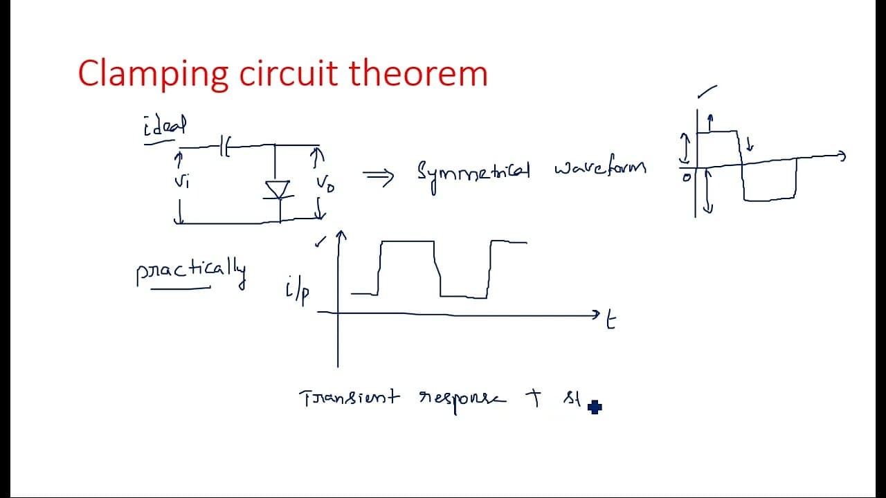
The clamping circuit theorem states that for any input waveform under steady state conditions, the ratio of the area under the output voltage curve in the forward direction to that in the reverse direction is equal to the ratio of their corresponding resistances. This theorem is crucial for designing practical clamping circuits to stabilize output, especially when dealing with unsymmetrical waveforms.
Transcript
hi everyone in this video you are going to learn about clamping circuit theorem before going into the clamping circuit theorem let us see what do you mean by clamper we know already clamper is nothing but a DC restorer or DC inserter or we can say it is a level shifter simply nothing but if any sinusoidal signal or any type of signal that we have t... Read More
Key Insights
- 📡 Clamping circuits serve as essential tools for adjusting signal components to desired voltage levels, ensuring proper signal processing.
- 🌍 Ideal clamping circuits are not fully practical; real-world applications require additional components for stability and accuracy.
- 🗜️ The forward and reverse current paths in clamping circuits exhibit distinct operational characteristics depending on waveform symmetry.
- 🗜️ The clamping circuit theorem provides a mathematical framework for understanding how input waveform areas relate to circuit resistance variations.
- 🖐️ Resistors play a pivotal role in mitigating transient responses in clamping circuits, particularly under non-ideal conditions.
- 🍵 The capacity of clamping circuits to effectively handle unsymmetrical signals highlights the need for careful design and analysis in electronics.
- 🥡 Designers must account for the time taken to reach steady state in unsymmetrical waveforms to avoid distortion in output signals.
Install to Summarize YouTube Videos and Get Transcripts
Explore YouTube Video Summarizer or Get YouTube Transcript Extractor
Questions & Answers
Q: What is the main function of a clamper in electronic circuits?
A clamper functions as a DC restorer or level shifter, effectively altering the baseline of an input signal. By using capacitors and diodes, a clamper can shift the entire waveform either upwards or downwards in relation to the ground level, depending on circuit configuration, which is critical for ensuring signal integrity in various applications.
Q: How does the difference between symmetrical and unsymmetrical waveforms affect clamping circuits?
Symmetrical waveforms have equal positive and negative peaks centered around the zero axis, allowing clamping circuits to function more effectively as they reach steady states quickly. Unsymmetrical waveforms, however, require additional time to stabilize, leading to a transient response that necessitates careful consideration in circuit design to avoid signal distortion.
Q: What are the practical modifications needed for clamping circuits when working with unsymmetrical waveforms?
Practical clamping circuits need to incorporate resistors in series and parallel configurations with the diode to enhance stability and control over the signal. These resistors help manage the diode's forward and reverse bias characteristics, ensuring the circuit can handle different waveform behaviors efficiently and reduce transient response times.
Q: Can clamping circuits handle all types of waveforms equally well?
While clamping circuits can work with a variety of waveforms—including sinusoidal, triangular, and square—performance may vary based on the waveform's characteristics. The presence of resistor networks becomes particularly crucial in ensuring effectiveness with unsymmetrical waveforms that challenge the stability of output signals.
Q: What information does the clamping circuit theorem provide regarding output voltages?
The clamping circuit theorem establishes a relationship between the areas under the output voltage curve during forward and reverse diode conduction. Specifically, it states that the ratio of these areas correlates to the resistances in the circuit, allowing for predictable and quantifiable behavior in the clamping process.
Q: Why is understanding clamping circuits important in electronics?
Understanding clamping circuits is fundamental for engineers and technicians as they form the basis of numerous applications in signal processing, waveform shaping, and data transmission. The principles of clamping ensure that signals maintain integrity and accuracy during alterations, which is vital in both analog and digital electronics.
Summary & Key Takeaways
-
The video introduces the concept of clamping circuits, explaining how they operate as level shifters for various input signals by using capacitors and diodes.
-
It contrasts ideal and practical clamping circuits, highlighting the need for resistors in real-world applications to stabilize the output signal, especially with unsymmetrical waveforms.
-
The clamping circuit theorem is presented, stating that the ratio of areas under the output voltage curve corresponds to the resistances in the circuit under consistent input waveform conditions.
Read in Other Languages (beta)
Share This Summary 📚
Summarize YouTube Videos and Get Video Transcripts with 1-Click
Try YouTube Summary with ChatGPT & Claude or YouTube Transcript Generator