Matched filter | Impluse response | Radar Systems | Lec-54
TL;DR
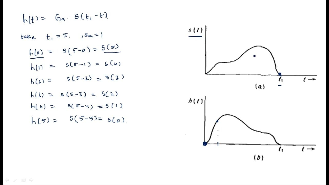
The impulse response of matched filters is a mirror image of the received signal.
Transcript
hi everyone in this video I will explain about the impulse response of the Matched filter so what do you mean by impulse response and what we have seen in the previous video we have studied the frequency response characteristics of this matched filter like h of f so what is Capital H of f Capital H of f is the frequency response of the Matched filt... Read More
Key Insights
- 🥳 The matched filter's frequency response is crucial for enhancing the signal-to-noise ratio in communications.
- ⌛ Understanding the conversion from frequency domain to time domain helps clarify the filter’s operational characteristics.
- ❓ The mathematical approach involves applying the inverse Fourier transform to derive the impulse response effectively.
- 🎮 The constant GA plays a significant role in scaling the filter’s output during the processing of signals.
- ⌛ The impulse response can be considered a time-domain representation, critical for understanding filter behavior over time.
- 🎨 The relationship between the impulse response and received signal offers insights into optimal filter design.
- 📞 Any changes in the received signal directly impact the impulse response, necessitating a tailored approach in matched filter applications.
Install to Summarize YouTube Videos and Get Transcripts
Explore YouTube Video Summarizer or Get YouTube Transcript Extractor
Questions & Answers
Q: What is the primary advantage of using a matched filter in signal processing?
The primary advantage of a matched filter is its ability to maximize the signal-to-noise ratio (SNR) in received signals. By matching its impulse response to the expected signal shape, it effectively enhances the detection of the desired signal amidst background noise, improving accuracy in communication systems.
Q: Can you explain the importance of the inverse Fourier transform in this context?
The inverse Fourier transform is crucial in converting the frequency response of a matched filter into the time domain impulse response. This transformation allows us to understand how the filter behaves over time, which is essential for determining how it interacts with incoming signals and improves the overall signal processing performance.
Q: How does the video relate impulse response to the received signal?
The video establishes that the impulse response of a matched filter is essentially the mirror image of the received signal. This relationship enables the matched filter to effectively correlate with the incoming signal, providing better detection and clarity in data recovery during signal processing tasks.
Q: What does the constant GA represent in the expressions given in the video?
In the context of the video, GA represents a constant factor that remains independent of frequency. It scales the impulse response and plays a crucial role in defining the overall strength of the filter's output, affecting how well the matched filter can process the received signals.
Q: What happens to the impulse response if the received signal changes?
If the received signal changes, the impulse response of the matched filter is affected correspondingly because it is derived from the frequency response of that signal. Therefore, any alteration in the received signal shape will lead to a different impulse response, potentially impacting the filter's performance in detecting and processing the new signals.
Q: What is the conclusion drawn about the impulse response's shape?
The conclusion drawn in the video is that the impulse response of the matched filter is functionally a mirror image of the received signal. This insight underscores the matched filter’s design, as its impulse response must complement the specific characteristics of the input signal for maximum effectiveness in signal detection.
Summary & Key Takeaways
-
The video explains the relationship between the frequency response and impulse response of matched filters, emphasizing the importance of maximizing the signal-to-noise ratio in received signals.
-
It details the mathematical process of deriving the impulse response from the frequency response using the inverse Fourier transform method, allowing viewers to understand time-domain representation.
-
Conclusively, the impulse response of a matched filter is determined to be the mirror image of the received signal, highlighting its critical role in filtering applications.
Read in Other Languages (beta)
Share This Summary 📚
Summarize YouTube Videos and Get Video Transcripts with 1-Click
Try YouTube Summary with ChatGPT & Claude or YouTube Transcript Generator